Engineering drawings sit at the center of every manufacturing and construction workflow, yet most teams still spend hours pulling measurements, materials, and details out of PDFs and scanned sheets. That slow, manual work creates delays, errors, and missed opportunities, especially as projects get more complex and timelines get tighter. This guide breaks down how engineering drawing extraction works, why it matters now more than ever, and how teams can use it to speed up RFQs, improve accuracy, and reduce rework across the board.
So let’s dive in!
What Is Engineering Drawing Extraction?
Engineering drawing extraction is the process of automatically reading technical drawings and turning every important detail inside them into structured data helping teams automate data extraction from engineering drawings.
Modern extraction covers a long list of drawing elements. It can read dimensions, tolerances, title-block, metadata, GD&T symbols, callouts, materials, and BOM tables. It can identify a note hidden near the corner of a scan or a symbol squeezed between two views. It can pick up tables that mix units. It can even detect links between different diagrams, like reference sheets or detail callouts.
This extraction supports many workflows. For example, RFQ teams can get instant measurements and part counts. BOM teams can skip the copy-paste marathon. QA teams can compare extracted values against the spec without typing each value by hand. Maintenance teams can look up the right part without reading through pages of diagrams. And digital twin initiatives can move faster because the source data is ready for use instead of sitting in a PDF.
The idea is simple: drawings stay as drawings, but the data inside them becomes instantly accessible.
Why Engineering Drawing Extraction Matters Now
The global engineering software market hit about $55.6 billion in 2024. It is heading toward $119.5 billion by 2029, growing at around 16.5% every year. The world is throwing more drawings, more models, and more documentation at teams than ever before. Yet most companies still run drawing workflows the old way.
Construction sees the cost first. Around 22% of rework comes from hidden or incorrect drawing details. That rework creates more than $14 billion in waste every year in the U.S. alone. This is the sort of cost that makes every project manager shake their head. Everyone feels it. Missed notes, wrong dimensions, outdated revisions, they stack up fast.
Despite all the software progress, more than 70% of AEC firms still rely on paper drawings or PDFs as their primary source of truth. Meanwhile, over 70% of manufacturers have adopted some level of process automation. This gap shows where drawing extraction sits today, right in the middle of a shift that is overdue.
Manual drawing reading slows everything down. RFQ teams read drawings line by line. Estimators jump across views, chasing material counts. Production teams copy values into tools. Engineers re-check the same dimensions because no one trusts a fast skim. The slowdown affects every part of a project, creating a quiet bottleneck that most leaders only see when work slips.
And the pressure is rising. Bid cycles shrink every year. Customers expect faster responses. Plants run leaner teams. Quality expectations rise even while people try to move faster. This combination pushes teams to work long evenings just to keep up.
Engineering drawing extraction helps break that cycle. It cuts the slowest part of the workflow — the reading. It reduces transcription mistakes. It gives teams a clear path to scale without hiring three more people for every new program. And it helps engineers spend more time solving problems instead of typing numbers.
Across manufacturing, construction, aerospace, automotive, and heavy industries, teams are realizing something simple: the drawing is not the problem. The reading is. Automation is the answer.
How Engineering Drawing Extraction Works (Step-by-Step)
Engineering drawing extraction may look complex from the outside, but under the hood, it follows a clear sequence. Each step solves a very specific task.
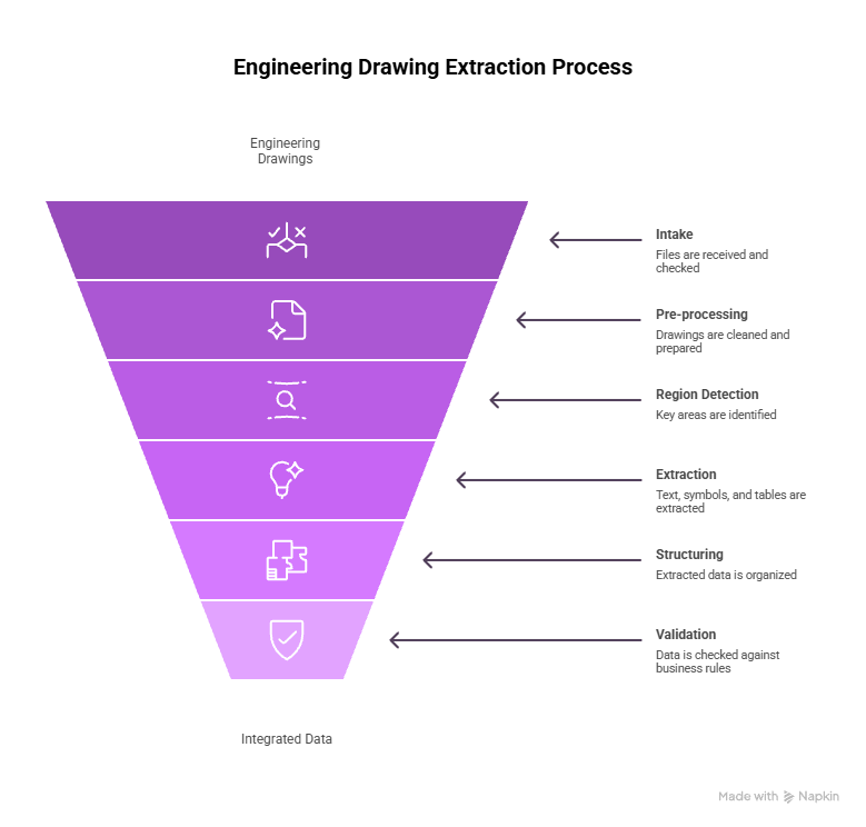
Intake: Files, Formats, and Quality Checks
The workflow begins with the input. Drawings come in many forms. PDF exports. CAD snapshots. Scanned paper sheets. Screenshots. Even images from field crews. The system first checks the file quality. It flags poor resolution, skew, shadows, and missing pages. It also categorizes the drawing, which helps choose the right extraction path. A P&ID needs different logic from a mechanical layout.
Pre-processing: Cleaning the Drawing
Before any extraction starts, the system prepares the image. It adjusts contrast. It straightens lines. It removes noise. It separates overlapping marks when possible. This stage is like wiping dust off a lens. Clean drawings lead to far better results.
Region Detection and Segmentation
Next, the system figures out where things are on the page. It finds the title block. It identifies views. It detects tables. It locates notes and callouts that might sit between two lines. It outlines different regions so they can be extracted separately. This is one of the trickiest parts of the entire workflow because drawings rarely follow a perfect layout.
Text, Symbol, and Table Extraction
Once the drawing is segmented, the system starts reading. It reads both printed and digital text. It interprets GD&T symbols. It detects arrows, leaders, and callouts. It understands geometric shapes that represent features. It extracts tables and reconstructs them into structured data. It handles units in different places. It picks up fractional dimensions and tolerances.
Structuring the Output
Extraction alone is not enough. The system must place each value in a structured format. This means creating rows, fields, and relationships. For example, linking a dimension to the correct feature. Linking a material to the correct BOM row. Or connecting a note to the relevant view.
Validation and Business Rules
Before the results leave the system, they pass through validation. The system checks ranges. It compares extracted values against expected patterns. It raises flags for missing items. It might also add automated comments or route questionable entries for review. This is where confidence scores help teams decide when to trust the extraction and when to verify.
Integrations: Getting Data Into Tools
Finally, the structured output moves into downstream systems. This could be ERP, CAD PLM, RFQ software, estimation tools, spreadsheets, or internal databases. The goal is simple: reduce typing and move data where people want it.
Key Challenges, and How Modern AI Handles Them
Engineering drawings present several technical hurdles. Modern AI handles many of them with steady and repeatable methods.
Low-Quality Scans, Handwriting, and Old Drawings
Many drawings arrive as low-resolution scans. Some include faded text, tilted pages, or compression noise. AI improves these inputs through contrast adjustment, line straightening, noise removal, and sharpening. Printed text extracts well after preprocessing. Handwriting varies widely. AI can read common patterns, but irregular handwriting still needs human review for reliability.
Overlapping Symbols, Dense Annotations, and Complex GD&T
Drawings often contain tight spacing. Leaders may cross each other. Symbols overlap. GD&T frames sit close to the edges. AI models trained on such layouts can separate lines, detect symbols, and interpret dense areas. Ambiguous regions are flagged for review instead of being forced into a wrong interpretation.
Non-Standard, Messy BOM Tables and Mixed Units
BOM tables follow no universal standard. Some include clear borders. Others use faint lines or inconsistent spacing. AI detects rows and columns through structure analysis instead of relying on table lines. It reads cells, assigns them to the right row, and captures item numbers, descriptions, and quantities. Mixed units across tables or views are detected and normalized.
Version Drift: ensuring you’re reading the latest revision
Drawings often go through multiple revisions. Files with similar names can lead teams to read outdated versions. AI identifies revision markers, compares differences across versions, and highlights mismatches. This reduces errors caused by using older sheets in quoting, planning, or production.
Multi-Diagram Relationships (P&IDs, Layouts, Details)
Large projects rely on diagram networks rather than single sheets. One sheet often points to another. AI detects these references and links related drawings. This helps teams follow information without searching manually across folders.
Dataset Scarcity and Annotation Cost — Why Pre-Trained Models Matter
Labeling drawings requires time and skilled engineers. Many teams do not have the bandwidth to label large datasets. Pre-trained models reduce the need for extensive labeling. They start with a general understanding and adapt to new drawing types through smaller tuning cycles. This cuts onboarding time and increases accuracy early in the rollout.
Security and IP Protection for Sensitive Drawings
Technical drawings contain core intellectual property. Good extraction systems follow strict security practices. They use encryption, role-based access control, and audit logs. Teams that require tighter control can use private cloud or on-prem deployments. This keeps sensitive drawings inside internal boundaries.

Implementation Checklist for Engineering Teams
The following is a clear rollout plan that helps teams adopt drawing extraction smoothly and avoid unnecessary steps.
Step 1: Assess your drawing landscape
Review the main drawing types you process. Identify formats, volume, scan quality, and variation across teams. List the recurring patterns and common issues. This sets the foundation for your first use case.
Step 2: Choose the First Use Case
Start with a workflow that has high volume and frequent repetition. RFQ extraction, BOM extraction, and part measurement tasks work well. These deliver measurable results within a short period and create internal confidence.
Step 3: Data & Annotation Plan
Even with pre-trained models, you may need a small annotated sample. Select a balanced set of drawings that represent your most common formats. Engineers can annotate a limited batch to support accuracy improvements without great effort.
Step 4: Pilot Design and Metrics
Run the pilot with real drawings and real workloads. Track extraction accuracy, throughput, and reduction in manual typing time. Measure consistency across multiple batches. Structured feedback helps improve model behavior during the early stages.
Step 5: Rollout and Change Management
Introduce the system gradually. Explain how extraction works, how flags appear, and how to review exceptions. Train teams on simple workflows first. Encourage feedback. Adoption improves when users understand why the change helps their day-to-day work.
Step 6: Scaling Across Plants and Regions
After a stable pilot, expand to other plant locations or teams. Document any stylistic differences in drawings across regions. Build a shared reference library so all teams benefit from updated learning.
Long-Term Scalability Strategies
After the initial deployment, long-term success depends on steady improvements.
Add More Drawing Types Over Time
Start with the most common drawing types. Add new categories slowly. The model improves as it sees more variety.
Use Feedback Loops
Reviewers should mark incorrect outputs. The system can learn from these corrections. Continuous feedback raises accuracy across future batches.
Standardize Drawing Practices
If teams control how new drawings are created, they can introduce simple standards. Clear dimension spacing, consistent view placement, or cleaner scanning guidelines improve extraction quality.
Monitor System Performance
Teams should review accuracy, throughput, and latency over time. If performance changes, they can adjust settings, retrain the model, or extend the annotation set.
Share Knowledge Across Sites
Larger companies can share best practices across plants or project teams. A small improvement discovered by one team can benefit everyone else.
ROI & Business Case for Engineering Drawing Extraction
Drawing extraction provides financial and operational gains across engineering, production, and field workflows.
Where the Savings Show Up
Time savings appear across multiple functions. RFQ teams reduce manual reading. Estimators speed up quantity extraction. Engineers avoid repetitive transcription. Production teams cut down on re-verification. QA reduces errors caused by missed details. When companies process high drawing volumes, these savings become significant.
Rework reduction also improves budgets. Missed tolerances, incomplete counts, or outdated revisions cause downstream issues. Extraction reduces such errors by capturing details consistently.
Measuring Accuracy, Throughput, and Stability
Accuracy is the most common metric, but it should not stand alone. Throughput shows how many drawings can be processed in a day. Stability shows how the system performs across drawing categories. A reliable solution maintains steady performance instead of swinging between high and low results.
Building the Internal Business Case
Stakeholders respond well to clear comparisons. Show how many hours a team spends on manual reading each week. Show how long RFQ preparation usually takes. Show sample outputs from extraction. Highlight early accuracy numbers and the time saved. A practical, measurable outcome builds support quickly.

Engineering Drawing Extraction in a Broader Automation Strategy
Drawing extraction does not stand alone. It becomes more effective when paired with other automation workflows. Many companies already automate invoice entry, material tracking, or scheduling tasks. Drawing extraction extends this automation into technical content that was previously too difficult to process automatically.
Connecting Drawings, Documents, and Data
Drawings connect to many other documents. RFQs link to BOMs. BOMs link to purchase orders. QA sheets link to part specifications. Maintenance schedules link to equipment diagrams. When drawing data becomes structured, these connections become easier to manage. Systems can match part numbers, compare dimensions, and verify materials without manual checks.
This reduces redundant work. Teams no longer enter the same values in multiple tools. Instead, data flows between systems in a stable and repeatable way.
When to Pair Drawing Extraction with Other IDP Workflows
Companies often see stronger results when they combine drawing extraction with other document automation. Here are common examples:
- RFQ Packages: Drawings, spec sheets, and vendor forms can be processed together, reducing cycle time.
- Manufacturing Packages: Drawings, routing sheets, and work instructions can be combined for complete extraction.
- Construction Submittals: Drawings, datasheets, and compliance documents can move through a single automated workflow.
- Maintenance Records: Diagrams, inspection logs, and part lists can sync into a central system.
When documents and drawings follow one path, teams avoid stitching together data from several sources.
How Infrrd Approaches Engineering Drawing Extraction
Infrrd’s approach to engineering drawing extraction is built around one idea: make the process faster and far less manual for engineering teams. By using models trained specifically on technical drawings, the system can read layouts, symbols, dimensions, and tables with high accuracy, without templates or heavy setup.
Template-Free Extraction and Pre-Trained Models for Drawings
Drawings vary by company, department, and region. Templates rarely match real-world conditions. Template-free extraction allows models to detect layout patterns dynamically. Pre-trained models shorten deployment time by learning from many drawing styles before the rollout begins. This reduces setup effort and helps teams start with good accuracy.
Handling Tolerances, GD&T, and Complex Objects with High Accuracy
Tolerances and GD&T symbols carry critical manufacturing information. The system detects these elements as structured objects, not loose text. It captures the value, symbol, and any linked notes. Complex shapes, sectional views, and callouts are read through visual detection rather than template matching. This helps maintain accuracy across varied drawing types.
No-Touch and Low-Touch Workflows for RFQs and BOMs
Once extraction stabilizes, teams can move from manual review to semi-automated review. High-confidence values pass through automatically. Low-confidence values go to a reviewer. This reduces typing and speeds up quoting and estimation. Over time, teams can expand this into near-zero-touch workflows for repetitive tasks.
Built-in Validation, Maker-Checker, and Audit Trails
Technical data often requires verification. Built-in validation checks for missing fields, incorrect units, and inconsistent values. Maker-checker workflows allow two-step review for sensitive projects. Audit trails capture every data change and decision, which helps during compliance checks or customer audits.
Example Outcomes (in ranges, not vendor-specific promises)
Companies commonly see:
- Large reductions in manual reading time
- Higher consistency in extracted dimensions and materials
- Clear identification of revision differences
- Faster RFQ preparation cycles
- Reduced rework triggered by missed details
Actual results vary by drawing quality, volume, and engineering process maturity.
How Teams Change Their Processes After Adoption
Drawing extraction changes daily work. Teams should expect shifts in routines and habits.
Less Manual Reading
Engineers spend less time reading every detail. They focus on exceptions, tricky elements, or safety-critical values. This reduces fatigue and lowers the chance of transcription errors.
Faster RFQ Turnaround
RFQ teams submit quotes faster because material counts, measurements, and part references appear automatically. Projects that once took days can move forward in hours.
More Consistent QA Work
QA teams rely on extracted data to compare drawings and specifications. They can focus on the parts that matter most instead of scanning entire sheets.
Centralized Drawing Data
Information becomes easier to search. Instead of hunting through folders, teams can filter drawings by material, part number, or revision.
Reduced Rework
As teams catch more details early, downstream rework decreases. Projects run with fewer delays.
Future Trends in Engineering Drawing Extraction
The field is advancing quickly, and new capabilities are emerging every year. As AI models become stronger and engineering workflows grow more digital, several important trends are beginning to shape the next phase of drawing extraction. These trends point to faster processing, higher accuracy, and deeper integration with the systems teams already rely on.
Higher Accuracy on Complex Symbols
Models continue to improve on GD&T, irregular shapes, and detailed annotations. This will raise the extraction quality for aerospace, automotive, and precision manufacturing.
Better Handling of Old or Degraded Drawings
Advances in image enhancement will support older archives. Companies with decades of paper drawings will gain more value as these models improve.
Deeper Links Between Drawings and 3D Models
As more teams adopt 3D workflows, extraction systems will map 2D data to 3D models. This helps digital twins and simulation systems access accurate information.
Automated Validation Beyond Simple Rules
Agentic systems will check relationships across drawings, specifications, BOMs, and routing sheets. This reduces manual cross-verification.
Seamless Integration into Engineering Apps
Extraction will move closer to design and planning tools. Teams will open a drawing and see extracted data instantly instead of running a separate step.
Final Note for Engineering and Construction Teams
Engineering drawing extraction takes a lot of the routine work off your plate. It cuts down on manual typing, speeds up RFQ turnaround, improves QA reviews, and turns unstructured drawing details into clean, usable data.
You still stay in control, AI handles the repetitive steps while engineers focus on exceptions, critical checks, and technical decisions. The result is a more predictable workload, fewer surprises, and smoother operations overall.
FAQs
Q1: What is engineering drawing extraction?
Engineering drawing extraction is the automated process of reading technical drawings and converting their details into structured data. It can process PDFs, scans, images, and CAD exports. It captures dimensions, tolerances, GD&T elements, materials, BOM tables, notes, and other annotations. The output becomes machine-readable data that can be used in RFQs, manufacturing planning, QA, or maintenance workflows.
Q2: What kinds of data can be extracted from engineering drawings?
The system can extract a wide set of information:
- Title-block data, such as drawing number, revision, date, and author
- Linear and radial dimensions
- Tolerances, deviation limits, and fits
- GD&T symbols and associated frames
- Material information
- BOM tables with item numbers, descriptions, and quantities
- Notes, callouts, and references
- Links between views or detail markers
This turns drawings into a structured set of fields instead of a static PDF.
Q3: How accurate is AI-based engineering drawing extraction?
Accuracy depends on drawing quality and consistency. Well-scanned drawings produce high accuracy. Blurry scans or handwritten items produce lower accuracy but can improve through feedback. In many cases, precision and recall exceed 90% for common categories like dimensions and GD&T. Accuracy rises as the system adapts to project-specific styles.
Q4: Can AI handle old or low-quality scanned drawings?
AI can handle many low-quality scans after preprocessing. It removes noise, improves clarity, and straightens lines. However, heavily distorted or faint drawings may require human review. Handwritten notes also vary widely and may not extract perfectly.
Q5: How is engineering drawing extraction different from standard OCR?
Standard OCR reads text in straight lines. Engineering drawing extraction reads text, geometry, symbols, layout, and relationships. It interprets the meaning of callouts, tables, and shapes. It outputs structured data rather than a simple block of text.
Q6: Which industries benefit most from automating drawing extraction?
Industries with heavy document and drawing usage benefit most. This includes manufacturing, construction, oil and gas, utilities, automotive, aerospace, industrial equipment, and other asset-focused operations. Faster extraction improves quoting, production planning, QA, procurement, and maintenance.
Q7: How does drawing extraction support RFQ and estimating teams?
Extraction speeds up measurement and quantity gathering. It reads dimensions, quantity markers, and materials from the drawing. This data can pre-fill takeoff sheets, BOMs, and RFQ templates. Cycle times shrink from days to minutes. Teams reduce errors caused by manual transcription.
Q8: What about security and IP protection for my drawings?
Reliable systems include encryption, access control, and audit logs. Sensitive industries can use private cloud or on-prem environments to keep drawings inside controlled networks. These measures support IP protection and compliance.
Q9: How long does it take to implement engineering drawing extraction?
Many teams can start a pilot in a few weeks. A full rollout usually takes a few months. Accuracy improves as the model adapts to drawing formats and feedback. Timeline depends on drawing volume, engineering workloads, and integration needs.
Q10: Do engineers still need to review the output?
Yes. Engineers review flagged fields, confirm critical elements, and verify dimensions that fall below confidence thresholds. AI reduces manual reading but does not eliminate engineering judgment. The goal is to shift engineers from data entry to oversight.

Priyanka Joy is a product writer at Infrrd who approaches automation tech like a curious detective. With a love for research and storytelling, she turns technical depth into clarity. When not writing, she’s immersed in dance, theatre, or crafting her next narrative.